Back
Project 2
—— STEP 1 ——
💁🏼 Program discussion and material preparation
We are going to use steering gear and ultrasonic sensors to make an auto-sensing trash can.
The envisaged solution can realize automatic switch by sensing the distance of the human hand, and use the steering gear to control the lid of the trash can to complete the automatic sensing of the trash can.
We chose the frog element as the carrier of the trash can, and also collected discarded express boxes for transformation as the outer shell of the box.
- Materials -
-
1x Arduino UNO
-
1x Servo motor
-
1x Buzzer
-
1x Ultrasonic sensor
-
1x 9v to 12v power supply

—— STEP 2 ——
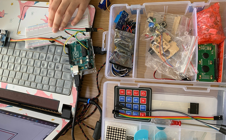
🙈 Initial attempt of circuit connection and code
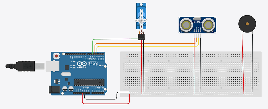
At first, we connected the ultrasonic sensor and the steering gear in series, and made a preliminary circuit connection.
Later, in order to make the whole program more interesting, we imported a buzzer to simulate the sound of frogs.
On this basis, we adjusted the wiring arrangement and modified the entire line to parallel.
After the ultrasonic sensor senses the human hand, the steering gear controls the opening of the lid of the box, and then makes a simulated frog call, the user throws garbage in, and the lid closes.

- Code -
#include <Servo.h> //servo库
Servo servo; //创建舵机对象来控制舵机
int trigPin = 5;
int echoPin = 6;
int servoPin = 7;
int buzz = 8;
long duration, dist, average;
long aver[3]; //array for average
void setup() {
//初始化串口通信以及连接SR04的引脚
Serial.begin(9600);
servo.attach(servoPin);//把连接在引脚7上的舵机赋予舵机对其控制
pinMode(trigPin, OUTPUT); //要检测引脚上输入的脉冲宽度,需要先设置为输入状态
pinMode(echoPin, INPUT);
pinMode(buzz, OUTPUT);
servo.write(0); //close cap on power on
delay(500);
servo.detach();
}
void measure() {
digitalWrite(10,HIGH);
digitalWrite(trigPin, HIGH); //产生一个10us的高脉冲去触发TrigPin
delayMicroseconds(2);
digitalWrite(trigPin, LOW);
delayMicroseconds(5);
digitalWrite(trigPin, HIGH);
pinMode(echoPin, INPUT);
duration = pulseIn(echoPin, HIGH);
dist = (duration/2) / 10; //obtain distance 检测脉冲宽度并测算出距离
}
void loop() {
for (int i=0;i<=2;i++) { //average distance
measure();
aver[i]=dist;
delay(10); //delay between measurements
}
dist=(aver[0]+aver[1]+aver[2])/3;
if ( dist<50 ) {
//Change distance as per your need
servo.attach(servoPin);
delay(1);
servo.write(0);
digitalWrite(buzz,HIGH);
delay(5);
digitalWrite(buzz,LOW);
delay(300);
digitalWrite(buzz,HIGH);
delay(20);
digitalWrite(buzz,LOW);
delay(300);
delay(2500);
servo.write(120);
delay(2500);
servo.detach();
}
//Serial.print(dist);
}
—— STEP 3 ——
👀 Prototype design
After initial connection of the steering gear, buzzer, sensor and initial editing of the code, we started the prototype design of the appearance of the trash can.
Conceptually, we adopt the frog design to make its external image cute, shorten the distance between the trash can and people, and better fit the theme of our team.


—— STEP 4 ——
💕Debugging and video shooting
After assembling the circuit and the frog shell, we start the debugging process of the trash can, and get the final automatic sensing frog trash can through repeated debugging of the induction delay time.
Finally, we shoot and edit the video.

—— Conclusions ——
QUESTION 1
The wiring is not clear enough, it is troublesome to check the wiring in a small space area.
QUESTION 2
At the beginning, we considered the connection of the circuit, the upload of the program, the appearance of the trash can, and the design of the interaction method, but in the process of doing it, I found that one point was not considered, that is, the location of the Arduino module in the trash can.
QUESTION 3
The line connection did not treat the positive and negative poles uniformly. All the 5v, 3.3v and GND pins on the arduino board were used up. Finally, the battery power was plugged in and the test failed. The most likely reason for Baidu is that the GND of the external power supply is not the same as the GND connected to each sensor.